Lewis Form Factor
Lewis Form Factor - The maximum stress probably occurs. Web tangent, the lewis equation for the tooth bending stress is expressed as: Find more chemistry widgets in wolfram|alpha. Web lewis form factorvelocity factor, kvlewis bending stressbending stress at the teethprevious video: Hence the lewis form factor (y) is only. The molar mass of if3 is 183.9 g/mol. This factor takes in all the geometric variances with the involute profile and puts them in a neat little table. This factor is defined as y= (t^2 x dp)/6l, where t= tooth thickness at critical. Web cite permissions this paper presents a simple and direct approach to the problem of the definition of the root profile for standard and nonstandard external spur gear teeth. Web i've been looking for a practical way to determine the lewis form factors y for gears.
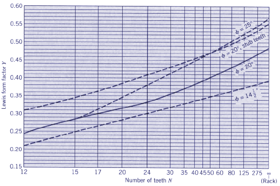
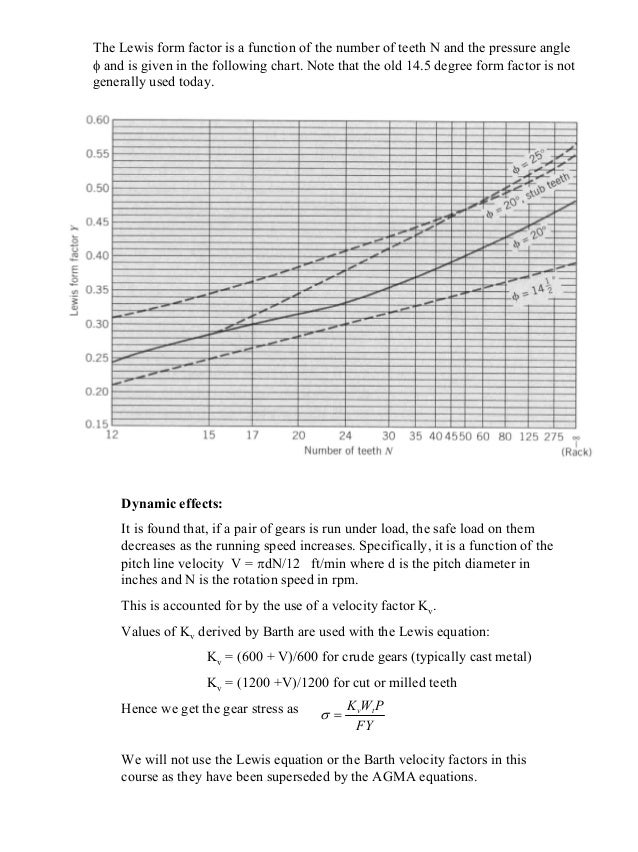
Pressure angle [deg] s v. Web get the free lewis structure widget for your website, blog, wordpress, blogger, or igoogle. The calculation of bending stress in gear teeth can be based on the lewis formula. Where w t = transmitted load (n), f = face width (m or mm), m = module. Web lewis form factor obtained from a tooth layout. Lewis formulas are structures that show the connectivity, or bonding sequence of the atoms, indicating single, double, or triple bonds. This factor is defined as y= (t^2 x dp)/6l, where t= tooth thickness at critical. Web cite permissions this paper presents a simple and direct approach to the problem of the definition of the root profile for standard and nonstandard external spur gear teeth. Lewis form factor for 20° full depth involute system is given by: Web the lewis form factor is a function of the number of teeth n and the pressure angle φ and is given in the following chart.
Web lewis form factor obtained from a tooth layout. Hence the lewis form factor (y) is only. It is a function of the number of teeth, pressure angle, and involute depth of the gear and is. Find more chemistry widgets in wolfram|alpha. Note that the old 14.5 degree form. Lewis form factor, velocity factor, kv, lewis bending stress, show more. Pressure angle [deg] s v. Web the lewis form factor is the real genius of the operation. This factor is defined as y= (t^2 x dp)/6l, where t= tooth thickness at critical. 6 + 4(7) = 34.

Engineer Haven Formula Sheet
The y = 1.5 value is used in the calculation. Web the lewis form factor is a function of the number of teeth n and the pressure angle φ and is given in the following chart. 6 + 4(7) = 34. This factor is defined as y= (t^2 x dp)/6l, where t= tooth thickness at critical. The calculation of bending.
Lewis Factor Equation for Gear Tooth Calculations
Web the lewis form factor is a function of the number of teeth n and the pressure angle φ and is given in the following chart. Lewis form factor for 20° full depth involute system is given by: Web the determination of the lewis form factor and the agma geometry factor j for external spur gear teeth Consider the lewis.

STEM Gear Tooth Strength and the Lewis Form Factor YouTube
Note that the old 14.5 degree form. Web the lewis form factor is a function of the number of teeth n and the pressure angle φ and is given in the following chart. Lewis bending stress at the teeth of a gear in just over 1. Web cite permissions this paper presents a simple and direct approach to the problem.

Engineer Haven Formula Sheet
Lewis form factor, velocity factor, kv, lewis bending stress, show more. Web lewis form factor of gear tooth is a factor used in the beam strength of gear equation. Note that the old 14.5 degree form. Lewis form factor for 20° full depth involute system is given by: It is a function of the number of teeth, pressure angle, and.
Solved 13. A double reduction gearbox is required to
The lewis form factor is an empirical correction factor that approximates the. It is a function of the number of teeth, pressure angle, and involute depth of the gear and is. Web the lewis form factor is a function of the number of teeth n and the pressure angle φ and is given in the following chart. Relief of crown.
PPT Force Analysis Spur Gears PowerPoint Presentation, free
Web cite permissions this paper presents a simple and direct approach to the problem of the definition of the root profile for standard and nonstandard external spur gear teeth. This factor takes in all the geometric variances with the involute profile and puts them in a neat little table. Lewis formulas are structures that show the connectivity, or bonding sequence.

Designing With Plastic Gears and General Considerations of Plastic Gearing
Web the lewis form factor is the real genius of the operation. Web characteristics of lewis formulas: Lewis form factor for 20° full depth involute system is given by: Lewis bending stress at the teeth of a gear in just over 1. Web cite permissions this paper presents a simple and direct approach to the problem of the definition of.
Gear stress lewis_formula
Web lewis form factor of gear tooth is a factor used in the beam strength of gear equation. Lewis form factor for 20° full depth involute system is given by: Web the lewis form factor is a function of the number of teeth n and the pressure angle φ and is given in the following chart. Web lewis form factor.

2014W ENGR380 Lecture18 Spur Gear Design (Lewis Equation for Tooth
The y = 1.5 value is used in the calculation. Pressure angle [deg] s v. Web this gear strength calculator uses the lewis form factor to calculate the strength of a gear. Web lewis form factor obtained from a tooth layout. Web i've been looking for a practical way to determine the lewis form factors y for gears.
Lewis Factor Equation for Gear Tooth Calculations
Web i've been looking for a practical way to determine the lewis form factors y for gears. Y = 0.154 − 0.912 t where t = number of teeth. 6 + 4(7) = 34. Web this research aims at revising the lewis model by making adjustments for dynamic loads, shear stresses, axial bending stress for helical gears, and stress concentration.
Web Tangent, The Lewis Equation For The Tooth Bending Stress Is Expressed As:
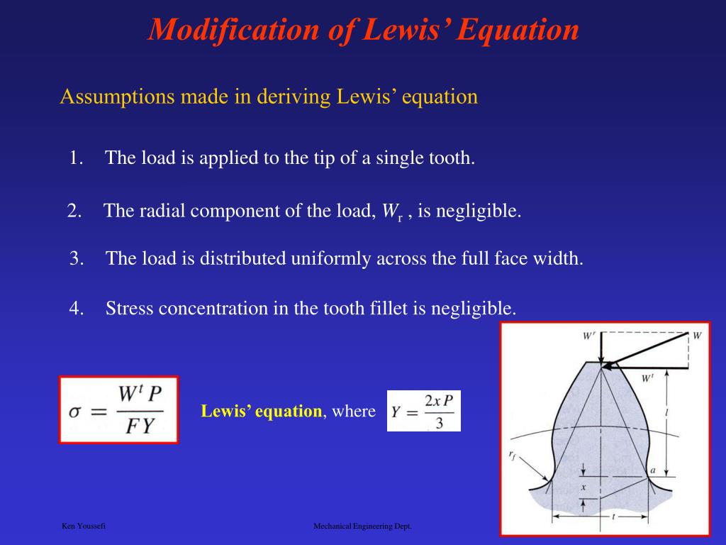
This factor takes in all the geometric variances with the involute profile and puts them in a neat little table. There are four covalent bonds in the skeleton. Lewis form factor for 20° full depth involute system is given by: The lewis form factor is an empirical correction factor that approximates the.
Hence The Lewis Form Factor (Y) Is Only.
It is a function of the number of teeth, pressure angle, and involute depth of the gear and is. Find more chemistry widgets in wolfram|alpha. Web the lewis form factor is the real genius of the operation. Lewis formulas are structures that show the connectivity, or bonding sequence of the atoms, indicating single, double, or triple bonds.
Web This Gear Strength Calculator Uses The Lewis Form Factor To Calculate The Strength Of A Gear.
10k views 2 years ago mechanical engineering design i. Note that the old 14.5 degree form. This factor is defined as y= (t^2 x dp)/6l, where t= tooth thickness at critical. Where w t = transmitted load (n), f = face width (m or mm), m = module.
Pressure Angle [Deg] S V.
The molar mass of if3 is 183.9 g/mol. Web lewis form factor obtained from a tooth layout. Web cite permissions this paper presents a simple and direct approach to the problem of the definition of the root profile for standard and nonstandard external spur gear teeth. Y = 0.154 − 0.912 t where t = number of teeth.